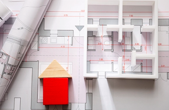
Technical drawings are essential in architecture, engineering, and construction (AEC). These serve as the foundation for creating, planning, and executing complex projects. Every structure, system, and process needs precise documentation to guide construction, ensuring everything aligns with the intended design. Without clear and detailed diagrams, there could be errors, inefficiencies, or unsafe practices.
Building Blueprints
Architectural drawings form the base of most AEC projects, offering some of the most widely used technical drawing examples in the industry. They provide a visual representation of a building’s design, including floor plans, elevations, sections, and details that describe the materials, finishes, and spatial arrangements. These diagrams are critical for architects, builders, and interior designers to understand the structure’s layout and aesthetic vision. They typically include the exact dimensions, placement of rooms, and spatial relationships, providing an overall vision of the building.
Construction Framework
Structural drawings depict the framework of a building, including foundations, columns, beams, and slabs. These designs ensure the integrity and safety of the structure by detailing how materials will support and withstand loads. Engineers rely on these to determine the types of materials to use and how they should be applied for the best results. They often include calculations for stress, load-bearing capacities, and reinforcement methods to maintain stability. Structural ones also indicate connections, joints, and any special structural elements necessary to ensure the building can handle both expected and unforeseen environmental forces.
Systems Layout
MEP (Mechanical, Electrical, and Plumbing) drawings represent the various systems that make a building functional. These cover everything from HVAC systems to electrical circuits and plumbing installations. MEP engineers use these detailed layouts to design the infrastructure that supports comfortable, safe, and efficient buildings. They ensure proper integration of each system into the overall building design without causing interference.
Site Planning
Civil engineering drawings are essential for planning and designing infrastructure projects such as roads, drainage systems, and land grading. These documents define the landscape of a project site, outlining grading, drainage, and other environmental factors to ensure the construction can proceed smoothly. They highlight key utilities, ensuring access to essential services like water, electricity, and sewer systems. These may also include the location of potential hazards like flood zones, wetlands, or unstable soil, which need to be avoided or mitigated.
Power Distribution
Electrical drawings focus on the wiring and power distribution systems within a building. These detailed diagrams help electricians plan the routing of electrical cables, circuits, outlets, and lighting. Electrical ones are indispensable in ensuring that power systems operate efficiently and safely throughout the building. They provide exact specifications for voltage requirements, circuit load distribution, and grounding systems to protect against electrical faults.
System Design
HVAC (Heating, Ventilation, and Air Conditioning) drawings provide layouts for the building’s climate control systems. These include details about ductwork, vent placement, and air circulation, ensuring comfortable temperatures and air quality. These technical diagrams help HVAC engineers plan systems to maximise energy efficiency and comfort. They specify system capacities, air flow rates, and the locations of critical components such as thermostats, dampers, and vents.
Plumbing Details
Piping drawings highlight the layout of a building’s plumbing systems. These documents show the routing of pipes for water, waste, and other fluid systems. They are crucial for ensuring the proper installation of these systems, as well as identifying the correct materials and connection methods. They include pipe sizes, pressures, and flow directions, ensuring there is no backflow or system failure.
Layout of the Site
Site plans are an integral part of technical drawings. They depict the full layout of a construction site, including the location of buildings, roads, landscaping, and utilities. Site plans also include topographical information, which helps guide construction teams during excavation and foundation work. These plans outline key elevation changes, slopes, and other geographical features that affect construction methods and equipment used. Site plans also consider local zoning regulations, setbacks, and accessibility requirements, ensuring the building fits within legal and practical boundaries.
Printer Role in Technical Drawings: Precision Support
- Printers are essential for producing large-format technical diagrams, ensuring detailed plans are accurately reproduced.
- High-quality printers provide scaled outputs that are manageable for contractors and engineers.
- These printers support various materials and paper sizes, preserving intricate details in the diagrams.
- They maintain colour accuracy, which is critical for differentiating between materials, systems, and construction stages.
- Large, crisp prints from these printers enable on-site teams to easily read and interpret every detail of the drawing.
Technical drawings are indispensable in AEC, facilitating the design, planning, and execution of every aspect of construction. From architectural blueprints to MEP layouts, these technical drawing examples play a critical role in ensuring a project’s success. Accurate and well-detailed technical ones help eliminate errors and optimise the construction process, leading to safer, more efficient outcomes.

